|
|
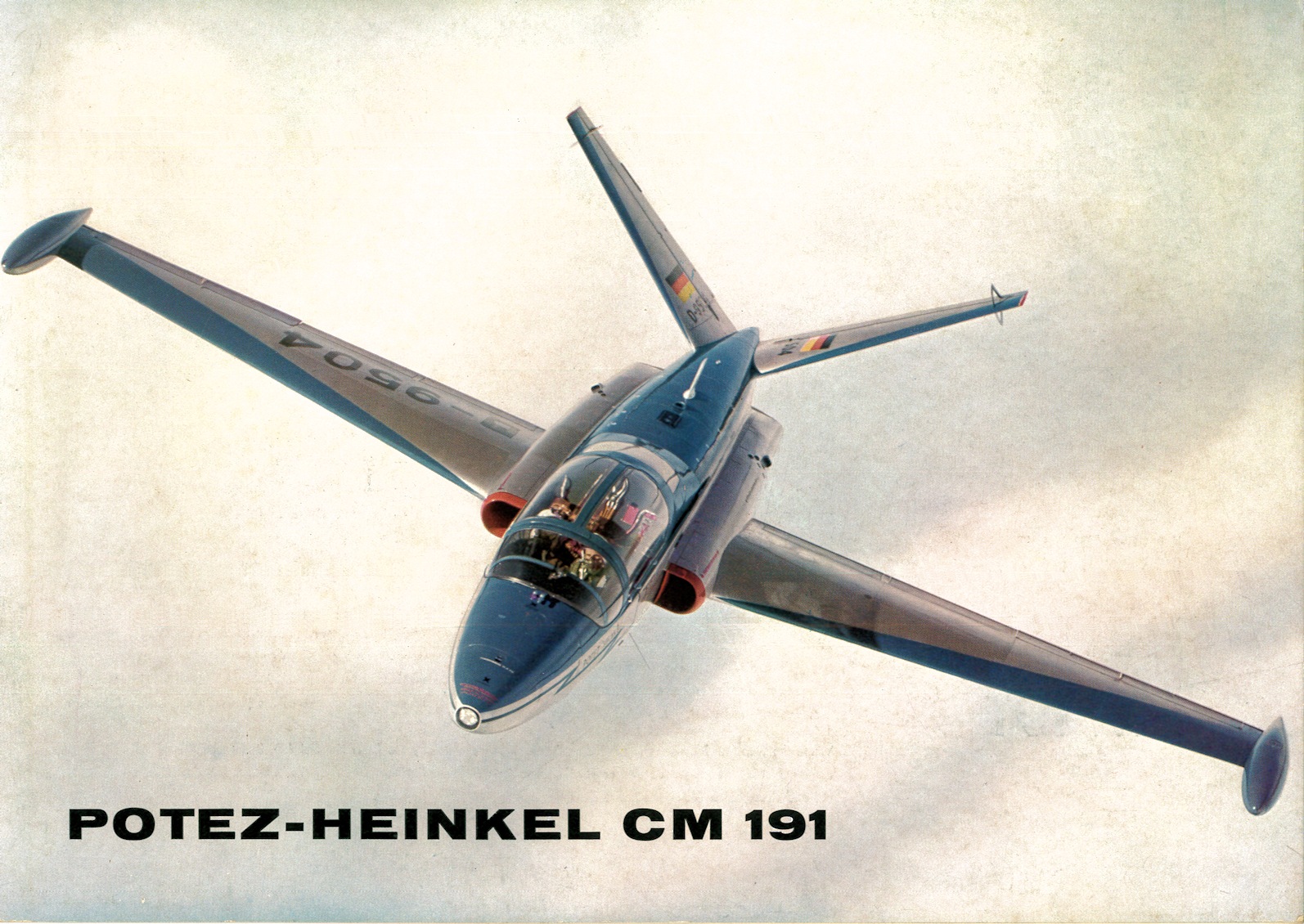
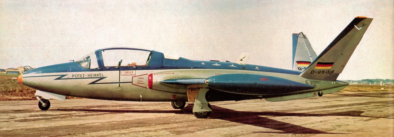
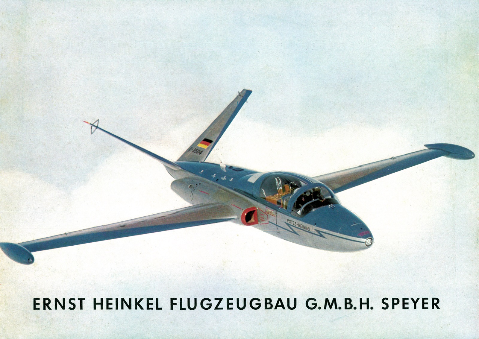
Potez-Heinkel C.M. 191 The CM 191 prototype made its first flight on March 19, 1962 in Toulouse with J. Grangette and P. Caneil at the controls. Only two prototypes were built, they represent one of the very first aeronautical cooperation between France and Germany. Two prototypes have been built. The first prototype is now flying in the US, registered as N8015Q. The second prototype which didn't fly is in the Technik Museum Speyer in Germany. The following information (and all images) is copied from a CM 191 brochure courtesy of A. Paul Vance Collection, Greater St. Louis Air & Space Museum. INTRODUCTION The four-seat twin-jet touring and liaison plane POTEZ-HEINKEL CM 191 has been developed from the well-known jet-trainer Fouga Magister CM 170, through cooperation of the firms Etablissements Henry Potez, Paris, and Ernst Heinkel Flugzeugbau GmbH, Speyer. The design of the aircraft was governed by the fundamental idea to transfer the recognized good qualities of the two-seat Fouga Magister to a four-seat airplane thus answering the demand for a reliable and economical aircraft in the four-seat category. While the firm Etablissements Henry Potez, Toulouse, was responsible for the project as well as for the aerodynamical and stress calculations, the entire design was made at the Heinkel Flugzeugbau GmbH in Speyer where the aircraft is also being manufactured. The POTEZ-HEINKEL CM 191 consequently provides a wide range of both private and military utilizations: Civil Aviation
Military Operations
The situation of spare parts supply and consequently maintenance is very favorable also because of the fact that the CM 191 uses numerous elements from the CM 170 which, in its turn, has been built and sold, respectively, in large quantities in Germany as well as in other countries. For the same reason maintenance of the jet-engines is secured. Within the territory of Germany, maintenance will be performed by the Ersnt Heikel AG, Stuttgart-Zuffenhausen, General Representative of Turboméca for the German Federal Republic.
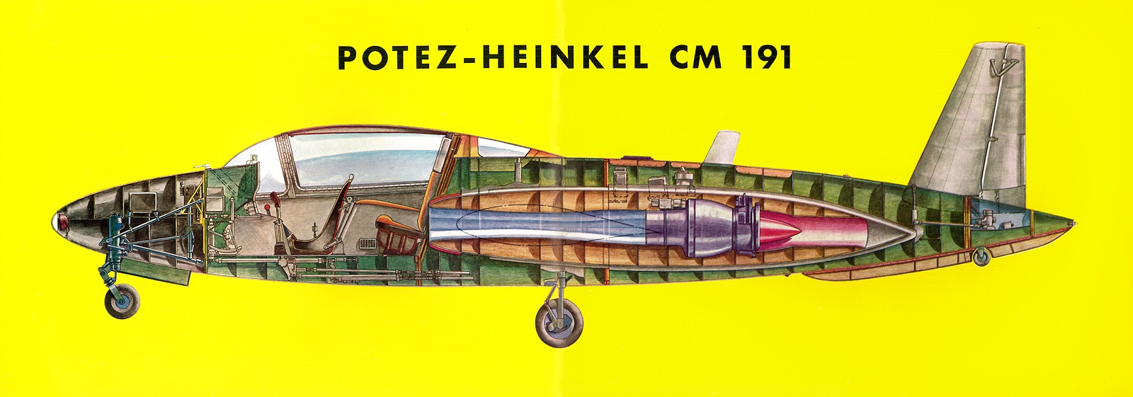
DESCRIPTION The turbo-jet aircraft Potez-Heinkel CM 191 is an all metal mid-wing monoplane with cantilever wings and a combined V-shaped rudder-elevator tail unit. The uncomplicated construction in connection with the clear and easily accessible arrangement of the structural elements marks the simple and economic conception which reduces maintenance to a minimum. In projecting the aircraft special importance has been attached to the requirement of being able to operate also from smaller airfields without the assistance of ground service.
The trapezoidal wings, with an aspect ratio of 7.67, sweptback leading edge, trailing edge not swept, are designed in the conventional monospar construction. Fowler-type landing flaps, hydraulically operated, warrant excellent low-speed flight characteristics without decreasing flight stability. The ailerons are statically and dynamically balanced and equipped with automatic Flettner-type trim tabs. Air brake segments are installed in each wing half and extend hydraulically from the upper and lower wing surfaces.
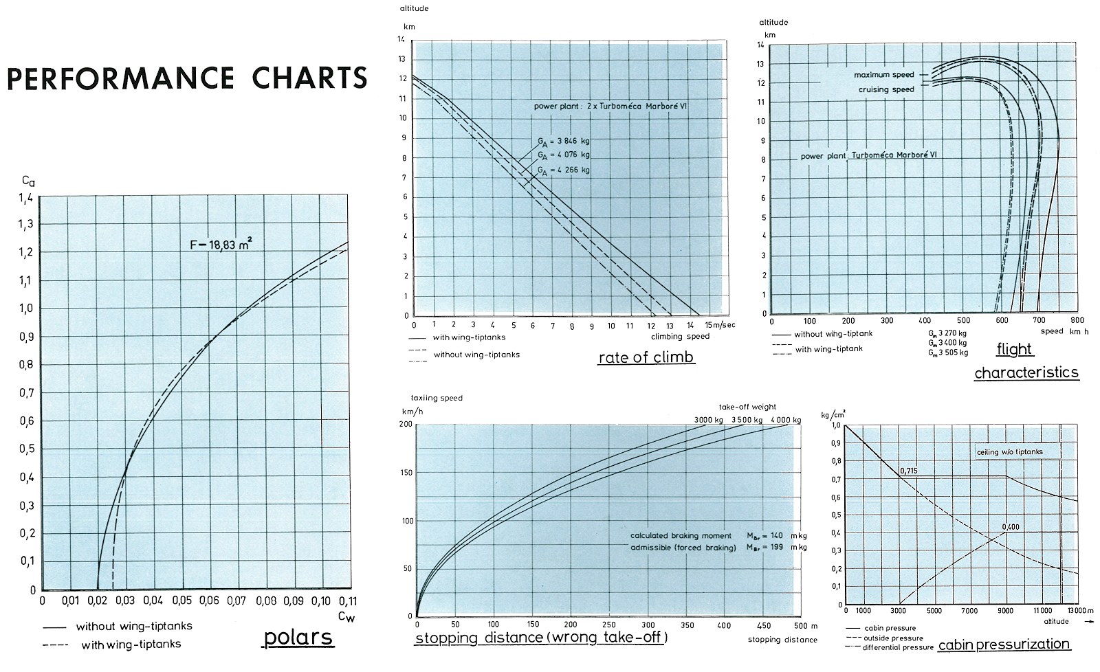
The monocoque fuselage uses a set of oval frames connected by four longerons to form the statical structure. The two jet-engines type Turboméca Marboré VI are installed laterally aft of the air intakes and partially imbedded in the sides of the fuselage center section. Besides, the wings are attached to the bulges of the air intakes, on both sides of the fuselage. The location of the jet-engines aft of the wing leading edges allows for convenient maintenance and easy accessibility upon removal of the cowlings. To facilitate maintenance and checking of flight controls and auxiliary equipment inspection doors have been provided for in the skin of the aircraft. A full-view canopy sliding backward for accessibility encloses the pressurized and air-conditionned cabin. The canopy is operated electro-mechanically, or manually, and may be jettissoned in case of emergency. By pressurization and air-conditioning the cabin pressure is adjusted from 0 m to 3000 m altitude relative to the outsied pressure. Above 3000 m the cabin pressure is kept constant decreasing only with a differential pressure of 0.4 kg/cm2 above an altitude of 9000 m. The air-conditioning system allows for individial temperature adjustment during flight. Special hot-air exhaust nozzles have been installed for defrosting and de-icing of front and side panes. The emergency oxygen supply of 14 litres will permit 3 hours of flight operations for 4 occupants. The four oxygen bottles are arranged in pairs under the rear seating bench elbow rests.
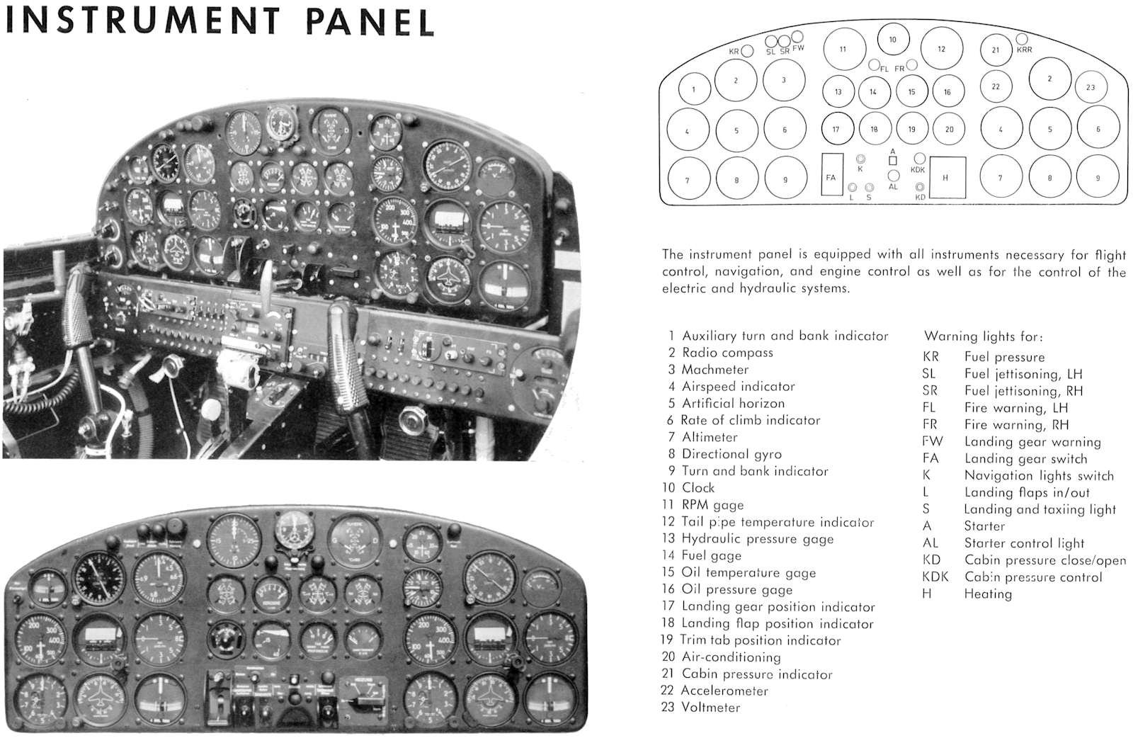
Very remarkable on the CM 191 is the monospar V-shaped tail unit consisting of two trapezoidal surfaces meeting at an angle of 110 degrees. Aerodynamical balance of elevator and directional controls is effected by axle offset and controlled trimmers with electrically controlled elevator trim tabs. The front-wheel type tricycle landing gear warrants safe landing and ground maneuvering stability because of the wide track of the main undercarriage. When boarding the aircraft the low above ground level makes the use of additional ground-based stairs unnecessary. Built-in steps closed by doors and located on both sides of the fuselage permit easy access to and leaving the cabin. The main landing gear mounted to shock struts is hydraulically retracted inwards intothe wings, and the nose gear towards aft into the fuselage nose housing. in case of emergency the landing gear may be operated manually by switching over to a hand-driven pump. In the standard version the CM 191 is equipped with two main fuel tanks located in the fuselage center section aft of the cabin with a total capacity of 1420 litres of fuel. To increase range the installation of wing tip tanks equipped with fuel jettisonning valves is optional. For special missions the rear seats may be removed and replaced by an additional auxilary fuel tank with 440 litres capacity. The aircraft is equipped with dual controls. The dual rudder pedals are adjustable in flight. All flight and nvagational instruments for pilot and co-pilot are arranged in two sets on a large shock-mounted instrument panel folding back for better installation and servicing. In single installation, engine control instruments, position indicators for landing gear and flaps, for elevator trimmers as well as for the air-conditioning plant are centrally located for easy reading from both front seats. The radio sets, oxygen regulators, and automatic fuses are installed on a lower fixed panel. The central control pedestal is well accessible from both seats. This unit contains the throttle controls, fire cocks with ignition switch, the switches for the emergency hydraulic system and for jettisonning of fuel, and the deicing pump. The 28 Volt direct current electrical system is powered by a 2500 Watts generator driven from the left engine through a drive shaft, and by an onboard battery with 35 Ampčres-hours capacity. The engines are started by the onboard battery or by a ground unit connected into the external power supply receptacle located above the right hand engine. The standard radio equipment consists of an UHF transmitter-receiver unit type AN/ARC-34, of a radio compass Lear ADF-102, and of an intercommunication set Bauknecht GEA IV-T-3-01. This unit enables also telephone communication with ground stations via UHF in case of emergency.
| |
|
Last update : 03FEB13 |